- Research
- Open access
- Published:
DCL 2.0: modular and reusable specification of architectural constraints
Journal of the Brazilian Computer Society volume 23, Article number: 12 (2017)
Abstract
Background
Due to the abstract nature of software architecture concepts, ensuring the correct implementation of architectural decisions is not a trivial task. Divergences between the planned architecture and source code may occur in the early stages of the software development, which denotes a phenomenon known as software architecture erosion. Architectural conformance checking techniques have been proposed to tackle the problem of divergences between the planned architecture and source code. Among such techniques, we can note the DCL (dependency constraint language), which is a domain-specific language that has interesting results in architectural conformance contexts. However, the current version of DCL has some limitations, such as lack of modularity and low degree of reuse, which may prevent its adoption in real software development scenarios. In this article, we extend DCL with a reusable, modular, and hierarchical specification.
Method
We propose and evaluate DCL 2.0—an extension of the original DCL—and its tool in a real-world development scenario of a large system used by a government branch of Minas Gerais, Brazil.
Result
We were able to detect 771 architectural violations where 74% of them could only be detected due to the new violation types proposed in DCL 2.0.
Conclusion
By using DCL 2.0 herein presented, it was possible to conclude the following: (i) DCL 2.0 proved importance in helping the development team consistently address violations, and (ii) after using DCL 2.0 for months, the number of architectural violations being committed into the system branches was reduced to zero. Therefore, we argue that DCL 2.0 can have a positive impact on the architectural conformance of systems.
Introduction
Software architecture is commonly considered a set of decisions and conventions that determine how to build a system, i.e., the architecture states the software’s fundamental parts as well as the responsibilities and interaction of those parts. The concept of software architecture is well discussed for some time [1]. There are studies that associate important software aspects (e.g., cost, evolution, performance, security, maintainability, etc.) to correct architectural decisions [2, 3]. There is also evidence that good architectural decisions can have positive impacts on software maintenance and evolution [4]. Another evidence that highlights the importance of architectural decisions is how several development and maintenance processes started to consider architectural decisions for their projects by creating techniques, models, and specifications to capture the architecture [5]. Therefore, we can decrease fault risks in software projects if we assure that architectural decisions are followed.
Due to the abstract nature of software engineering concepts, it is not a trivial task to assure the correct implementation of architectural decisions. Some studies indicate that divergences between source code and the planned architecture can occur in the beginning stages of the development process [4, 6]. Other studies present scenarios where software source code, during its evolution, gradually loses its adherence to the architecture; this phenomenon is known as software architecture erosion [7–9]. In other words, after several maintenance and evolution tasks, architectural rules and decisions are ignored leading to architectural violations. Architectural violations are classified into two groups: (i) structural violations, which refer to inconsistencies related to component creation, i.e., violations occur when the component location, naming, or characterization diverge from the planned architecture; and (ii) relational violations, which refer to inconsistencies in the relations among components.
In object-oriented systems, the relations among components are accessing attributes, calling methods, inheriting types, and instantiating objects. Figure 1 shows two types of violations occurring in a hypothetical scenario. On the left side, we can see the planned architectural model. On the right side, we see a source code projection of such system. Violation #1 is a structural violation because component Baz did not exist in the planned architecture’s hierarchical structure. Violation #2 is a relational violation because, in the planned architecture, Foo should not make method calls to Bar.

Structural and relational violations. The planned architecture (left) and the implemented architecture with violations (right)
There are architectural conformance verification techniques proposed to tackle the problem of finding divergences between the source code and the planned architecture [10–12]. Dependency constraint language (DCL) is a declarative language to verify the dependencies among modules in object-oriented systems [12]. DCL was designed to model architecture components as well as the constraints among such components. DCL has the following positive points: (i) expressiveness, DCL supports a wide variety of architectural constraints; (ii) abstraction level, DCL provides a limited support to associate specific source code parts (low level) with abstract elements (high level) by using a module definition; and (iii) applicability, once it is an easy to learn language. Although its many advantages, DCL also has some characteristics that may hinder its adoption in real software development scenarios, as follows:
-
Coupling: the DCL architectural specification is stored in a text file placed in the target project structure, which complicates reuse of the specification to other projects.
-
Monolithic: the architectural specification is created in a monolithic manner and hence difficult to maintain, especially in larger and modularized systems.
-
Non-hierarchical modeling: DCL does not support the creation of hierarchical relations among architectural elements. Since architectural models are inherently hierarchical, this limits capturing these models with better accuracy.
-
Structure constraints: even though DCL has a variety of constraints to control architectural violations, it still lacks some structure constraints to better specify the system’s architecture.
-
Limited of conceptual traceability: DCL provides limited support to model relations among conceptual elements from a system and its source code. These conceptual elements are important to provide context for the architecture.
In this context, this paper proposes an extension of DCL, called DCL 2.0, which we implemented the following features and concepts to fill the gaps from the previous version and to increase reusability:
-
Hierarchical modeling: to allow a more faithful capture of the architectural logical models. It also facilitates the architectural visualization in different formats. Moreover, DCL 2.0 architecture models can be composed of any type of artifact found in a software development project, e.g., classes, projects, packages, documentations, etc.
-
New constraints and traceability: the new constraints provide more options to tackle structural violations. We also provide traceability among conceptual constraints and source code artifacts.
-
Decoupling: the modeled specification is completely decoupled from the target project, which promotes reuse and evolution of the architectural specification.
-
Modularization: the specifications are modular which favors reuse among components by using references.
-
Tool support: facilitates common activities to specify and to design the architecture, such as editing specifications, and validating and visualizing the architecture.
We evaluated DCL 2.0 by checking the architectural conformity of a large system from the Minas Gerais state government in Brazil. The results show that DCL 2.0 can precisely capture the system’s architectural model. Moreover, the language inhibited the creation of new architectural violations by developers during the analyzed period. We detected 771 architectural violations on the analyzed system; 74% of those violations were only detected by the new constraints proposed in DCL 2.0. After the study, our architectural conformance tool was incorporated to the software development process of the company that maintains the evaluated system.
The three main contributions of this paper are summarized as follows: (i) the DCL 2.0 language, which was designed for a better usability and reuse than other architectural conformance techniques; (ii) our experimental process used for the evaluation, which monitors architects and developers on tasks related to handling architectural violations; (iii) the implemented tool with features to improve the user’s usability and facilitate the adoption of DCL 2.0 in development teams.
This paper is an extended version of our first work on DCL 2.0 [13] where we highlight the following improvements: (i) new section comparing architectural conformance techniques and their main characteristics; (ii) new section detailing our implemented tool for DCL 2.0; (iii) a more complete and detailed evaluation section; and (iv) a more exhaustive related work.
The remainder of this paper is organized as follows. The “Background” section presents basic concepts to better understand our proposed solution. The “Proposed language: DCL 2.0” section presents DCL 2.0, the language’s extension with modular specification, hierarchical relations, and better reusability. The “Tool support: DCL2Check” section shows DCL2Check, a tool that implements our proposed solution. In the “ Evaluation” section, we evaluated the use of DCL 2.0 in a large system developed for the Minas Gerais government state. The “Related work” section presents the related work. Finally, the “Conclusion” section concludes the paper and outlines future work.
Background
In this section, we present all concepts required to fully understand our approach. The “Architectural conformance checking” section briefly describes the theory on architectural conformance checking. The “Conformance techniques comparison” section performs a general comparison on architectural conformance techniques. Finally, the “DCL” section presents DCL, the language we have extended in this paper.
Architectural conformance checking
Software architecture is usually the main artifact designed during software development for reasoning about software properties either functional or non-functional such as availability or modifiability. Design and architectural decisions have large influence on several implementation artifacts. When developers mistakenly violate these decisions, this leads to the software architecture erosion phenomenon. This gap between implementation and architecture causes the system to fail to satisfy some of the intended nonfunctional properties [14].
Architectural conformance checking is a process that investigates consistency between different artifacts in a wide scope. The main use is to ensure that the software is implemented according to the planned architecture, which is the foremost high-level artifact. Architectural compliance can be performed in several ways, such as from a high-level model to the source code, and between models at similar abstraction levels. It can also be classified as (i) static and (ii) dynamic. Static means that the source code is statically compared to the software’s architecture view. On the other hand, dynamic means that the source code is analyzed at runtime. Architectural verification evaluates dependencies between components and are divided into:
-
Convergence: when a relation prescribed by the high-level model is followed by the source code.
-
Divergence: when a relation not prescribed by the high-level model exists in the source code.
-
Absence: when a relation prescribed by the high-level model does not exist in the source code.
After the dependencies have been checked, the next step is to fix the architectural violations found by the verification process. The correction must be consistent with the system architecture. On the other hand, this correction task is time-consuming, especially when the violations have been accumulated for a long time period. Therefore, the task of correcting architectural violations is important to prevent and to reverse architectural erosion [15].
There are several techniques that aim to support architectural conformance tasks; each one has its positive and negative aspects. In the “Conformance techniques comparison” section, we conduct a brief comparison of the main techniques.
Conformance techniques comparison
In this section, we present an overview of related architectural conformance techniques to summarize their main characteristics for an easy comparison. Table 1 presents the main techniques according to our study and seven characteristics (modularity, abstraction, dependency, structure, reuse, visualization, and easy to learn) each one supports. If the paper describing the technique explicitly stated, the characteristic we marked “Yes.” If the paper does not describe a characteristic but in our analysis, we found some alternative feature that could be used in the same context, then we marked “Partial.” Otherwise, we marked “No.”
Modularity analyzes if the technique supports modular architectural specifications or modeling. This is an important aspect because it allows the specification of independent and flexible models. Abstraction verifies if the technique provides different abstraction levels when specifying architectural components. Lack of abstraction features may over complicate the architectural specification of systems with a large amount of lower level components. Dependency checks whether the technique provides some way to specify dependencies between components. Most architectural conformance techniques rely on dependencies definitions because they are intuitive. Structure refers to whether the technique captures structural violations (i.e., inconsistencies related to component creation) or not. We claim (and we further empirically demonstrate) that techniques that capture structural violations are likely to uncover more violations. Reuse checks if there are features specifically designed to reuse architectural specifications for other systems. This decouples the architecture specification and decreases the effort in specifying architectures for other systems. Visualization can be used to assess if the technique provides a tool support to visualize the intended architecture. It can help users to better understand the system architecture. Easy to learn analyzes the learning curve required for understanding the technique and for specifying the intended architecture. Techniques that are easier to learn facilitate their adoption.
Dependency constraint language (DCL)
DCL [12] major advantage consists in how easy it is to learn the language and how easy it is to be used for architectural conformance check. DCL relies on simple concepts, which requires few keywords combined to create architectural restrictions. The language favors expressiveness, which allows to model several types of restrictions. There is another important point, DCL is non-intrusive and does not require any source code modification. DCL is a feasible solution to monitor and control dependencies on object-oriented systems. However, DCL is not a complete language for architectural specification. DCL main focus is on dependencies control that may not capture all architectural aspects, such as structural characteristics [16]. In DCL, the architectural definitions are monolithic and lack modularity, which can cause problems for the architectural specification [8]. For example, DCL does not support a way to specify components in a hierarchical manner, which is a common occurrence when modeling object-oriented systems [17, 18]. Finally, DCL does not explicitly show architectural convergences, which are an important factor to understand the system architecture [11].
Reflection model
Reflection model [11] is a popular technique for architectural conformance since there are many studies on this particular topic. A strong positive point on adopting reflection models is that their concepts are intuitive and easily adaptable to different scenarios [4, 19, 20]. On the other hand, this technique does not show explicit concern for reusability, and trying to reuse reflection models in different system with similar architectures is not a simple task. Therefore, this lack of reusability can be a barrier to adopt this technique for architectural conformance [19].
Vespucci
Vespucci [8] has many interesting features, such as modular architectural definition and components reuse. Vespucci also allows the modeling of different abstraction levels by using ensembles and slices. The tool support is a negative point for this technique, which has a sub-par documentation and it appears to be inactive. We also found very few studies to assess the applicability of this technique in real scenarios.
Dependency structure matrix (DSM)
DSM [21] is easy to employ on architectural conformance tasks due to its inherent simplicity. Architects require little effort to acquire a general overview of the system architecture, which also shows the dependencies between components [7, 22]. Unlike other techniques, DSM can create a dependency matrix without relying on mapping higher level components. On the other hand, this characteristic undermines the reuse to other systems, since there is not a formalization on higher level concepts. DSM also does not support explicit architectural specification, which also hinders reuse.
Source code query languages (SCQL)
There are source code query languages adapted to architectural conformance, for example the SCQL [23]. This technique is very flexible in searching for undesirable code pattern (i.e., architectural violations). SCQL similarity to SQL facilitates its adoption, although the features design for object-oriented adds a significant complexity to the language. The language is counter-intuitive to model architectural definitions since every aspect of SCQL is expressed by source code queries. Another problem is that SCQL does not support abstraction for higher level components; it only works at source code level.
Design tests
Design tests [24] employ the concept of unit testing applied to architectural compliance. Since it is based on unit testing, this technique is easy to learn for users who are familiar with testing frameworks. This technique does not facilitate architectural modeling, mainly because it is not intuitive to specify architectural details by using tests. Moreover, design tests do not have features explicitly designed for higher level abstraction.
Framework-specific model language (FSML)
FSML [25] goal is to model architecture focused on frameworks. The technique does not control structural dependencies or relations, and uses framework instantiation for architectural conformance. The instantiation feature favors reuse, since it is possible to instantiate architectural models as many times as necessary. On the other hand, the framework-based architectural conformance is not easy to learn.
ArchLint
ArchLint [9, 26] automatically extracts architectural rules from source code version history. Therefore, ArchLint is well suited when the system documentation is not well kept. This is a very strong point that favors the adoption of ArchLint. On the other hand, ArchLint requires a higher level architectural model to map the source code into architectural specifications, which may compromise its adoption by inexperienced users. Since ArchLint automatically extracts the architectural specification from the source code, it does not (and is not expected to) promote reuse or modularity for its specifications.
Object constraint language (OCL)
OCL [27] is an UML standard that allows the specification of constraints among objects. This technique has the advantage of being integrated with UML models, and it features object-oriented features such as inheritance, and abstraction. On the other hand, OCL lacks usability which makes it more difficult to learn and adopt. Since it is a standard, OCL does not offer any type of constraint visualization. Moreover, OCL reusability depends on whether you can reuse the UML models integrated with it, and as such this might not be a strong suit for this technique.
Architecture description language (ADL)
ADL [28, 29] is a broader term that defines a language that provides means to specify architectural and its constraints. We can see that OCL, DCL, and others can be considered ADLs, as they fall into its definition. However, for this category, we are analyzing a set of ADLs that were not previously discussed.
Armani [30] is an old ADL with similar characteristics and disadvantages that most ADLs share. More specifically, Armani supports different abstraction levels, the specification of dependencies, and limited modular specifications. However, it does not capture structure violations, it does not favor reuse, it has no support to visualize the architecture or the constraints, and it learnability was not a concern when the language was designed.
Alloy [29] defines an ADL that maps the architectural language definition into a model that can be more easily verified for architectural conformance. Unlike other ADLs, alloy does provide a limited support to capture some structural violations.
CLACS [28] uses the concepts of component-based software development to model the architectural specifications. CLACS was specifically designed to tackle the lack of reuse faced by most ADLs.
Critical assessment
Most techniques do not explicitly concern with architectural reusability. Moreover, few techniques partially support the capture of structural violations while the majority does not support it at all. We can also see little support for modular specifications. Therefore, most architectural conformance techniques lack on these three characteristics: reuse, structure, and modularity. On the other hand, for the positive points, most techniques explicitly specify and monitor dependencies between components. There is also a general concern to provide other abstraction levels when modeling architectures.
DCL
DCL is a declarative language aimed to verify dependencies among modules from object-oriented systems [12]. The language restricts the dependencies among modules by using a set of architectural rules. Basically, each rule has two elements and one relation between them, as follows: M A cannot-extend M B
Constraint M A cannot-extend M B indicates that classes from module M A cannot extend classes from module M B . All DCL constraints follow the same syntax. Indeed, this simple and intuitive syntax is one of the main advantages of DCL. Therefore, once the system architect knows the project’s architectural characteristics, it becomes a relatively simple process to employ DCL to model architectural constraints.
We need to follow a few steps to use DCL for architectural specification. First, we define the modules, which are the high-level components in DCL. Then, we define the mapping of classes into modules, i.e., in this step, we specify the module that represents source code classes. Finally, we define the constraints between each pair of modules.
Once we have the DCL architectural specification, we can use tools to read such specification and verify the source code for architectural violations. Basically, the specification is created by modules and the constraints between a pair of modules. A module is a set of classes, as shown in Listing 1.

In the example, module Math (line 1) represents only one class (java.lang.Math). In line 2, module Exception represents two classes: java.lang.RuntimeException and java.io.IOException. In line 3, JavaUtil module that represents all classes from the java.util package. In line 4, module JavaSwing refers to every type defined in javax.swing package or sub-packages.
DCL classifies its violations into two groups: divergences and absences. A divergence violation occurs when an existing dependency in the source code violates the architectural model. DCL provides the definition of the following kinds of constraints between modules:
-
Only classes from module A can depend on types defined in module B, where the possible dependencies are as follows:
-
only A can-access B: only classes declared in module A can access (calling methods, reading or writing to fields) non-private members of classes declared in module B.
-
only A can-declare B: only classes declared in module A can declare variables of types declared in module B.
-
only A can-handle B: only classes declared in module A can access and declare variables of types declared in module B. This is an abbreviation for only A can-access, can-declare B.
-
only A can-create B: only classes declared in module A can create objects of classes declared in module B.
-
only A can-extend B: only classes declared in module A can extend classes declared in module B.
-
only A can-implement B: only classes declared in module A can implement interfaces declared in module B.
-
only A can-derive B: only classes declared in module A can extend a class or implement an interface declared in module B. In other words, this is an abbreviation for only A can-extend, can-implement B.
-
only A can-throw B: only methods from classes declared in module A can return with exceptions declared in module B raised.
-
only A can-useannotation B: only classes declared in module A can use annotations declared in module B.
-
-
Classes declared in module A can depend only on types defined in module B, where the dependencies that can be prescribed are similar to those described for the only-can constraint (declare, handle, create, extend, implement, derive, throw, and useannotation). For example, A can-access-only B defines that classes declared in module A can access only non-private members of classes declared in module B.
-
Classes declared in module A cannot depend on types defined in module B. The dependencies that can be forbidden are similar to those described the only-can constraint. For example, A cannot-create B defines that no classes declared in module A can create objects of classes declared in module B.
On the other hand, an absence violation occurs when the source code does not follow a dependency that is prescribed by the architectural model. In order to capture absences, DCL supports the definition of the following constraints:
-
Classes declared in module A must depends on types defined in module B, where the dependencies that can be prescribed are similar to those described for divergence violations. For example, A must-derive B defines that all classes declared in module A must extend a class or implement an interface declared in module B.
Figure 2 summarizes the language syntax.

DCL constraints (adapted from [12])
DCLsuite is a plug-in to the Eclipse Integrated Development Environment (IDE). It implements DCL to perform architectural conformance verification. DCLsuite has an editor to create and edit specifications, which are stored in a file with the .dcl extension. The .dcl file must be placed in the root directory of the target project. In fact, DCLsuite reads this file to analyze the source code searching for architectural violations, i.e., it automatically checks the source code. The violations found by DCLsuite are presented as errors in the Eclipse Problems tab interface.
DCL also has an extension, called DCLfix, that provides recommendations for developers to solve problems related to architectural erosion [15, 31]. Moreover, DCLfix suggests refactoring recommendations to the violations that were detected during the architectural verification done by DCL. Another DCL-based tool, called ArchRuby, was proposed to verify the architectural conformance of dynamically typed languages [32].
In the remainder of this paper, we refer to the original DCL language as DCL 1.0 to avoid being mistaken with our proposed extension.
Proposed language: DCL 2.0
In this paper, we propose DCL 2.0, an extension on DCL 1.0 by introducing modular, reusable, and hierarchical specification models. The objective is to improve the original DCL language with the detection of new types of architectural violations. We also improved several other language aspects such as the architectural specification, documentation, and visualization. Moreover, our motivation to propose an evolution for DCL 1.0 is to enhance it with important features to be more effective in real software development scenarios. Table 2 highlights the main features reworked by our proposed language—DCL 2.0—and their situation in the original DCL 1.0.
Hierarchical and modular specification
Software development usually uses artifacts composed of components from a higher abstraction level to represent the system’s architecture. This situation is more common in the beginning stages of the development, where the architectural requirements are still unclear. As the development progresses, the architecture is further detailed and its higher level components are decomposed into smaller ones (e.g., sub-modules, packages, directories, classes, and files). We can observe a hierarchical pattern when we detail such smaller components. Architectural models reflect the system’s internal structure and they can be used to communicate the software architecture [7, 8]. A few other approaches provide hierarchical specification arguing that a hierarchical model is easier to work considering components from different abstraction levels [7, 8].
Our proposed language, DCL 2.0, supports hierarchical and modular specification. By contrast, DCL 1.0 only supports a monolithic and flat specification where each module or component is defined independently from each other.
Figure 3 represents the logical (a) and physical (b) structure for a hypothetical system. Listing 2 shows the specification using DCL 2.0 for the same fictitious system. We can see the following three models have a hierarchical nature: (i) the logical model (Fig. 3 a), (ii) the physical model (Fig. 3 b), and the DCL 2.0 specification (Listing 2). On the other hand, DCL 1.0 would define every component isolated from each other, and without any indication that a component could include or be a part of other components.

Hypothetical system models: a logical model and b physical model
In Listing 2, we defined the component foo (line 2) for the example architecture. DCL 2.0 allows hierarchical specification of modules; in this case, foo contains other three components: entities (line 3), constants (line 10), and utils (line 17). Each component can map and group lower level artifacts (source code and other files) into a higher abstraction definition. For instance, inside the component entities, we map file names that begin with “Ent” to the newly defined Entity abstraction (line 4), and all architectural constraints this component follows (lines 5 to 7). We can also see that Fig. 3 shows an example of this representation where EntCar.java and EntPerson.java are classified as entities.
A software modularity is defined as a way to implement more flexible and comprehensible systems, which impacts directly on its maintenance tasks [33]. In software architecture, modularity is also very important. We can observe this importance in the architectural model 4+1, where views like logical view and implementation view capture modularity aspects [5]. Although the benefits of modularization are clear, for architectural conformance and specification, there is little discussion on this front. As we explain in related work (the “Related work” section), most architectural specifications are monolithic in nature.
DCL 2.0 implements a modular specification by using a cross-reference mechanism, where an element defined in a specification file can be referenced by another file. As already illustrated in Listing 2, we can see component plataform.java.lang (lines 6, 13, and 20) were not defined in the current file, they are references. One of the main advantages for this modularity specification in DCL 2.0 is the reuse of architectural components, i.e., frameworks, APIs, and libraries can have its components specified only once and reused by other projects.
DCL 2.0 also requires a more formal specification than other languages. For example, we can observe the ignore keyword, which informs that component doc should not be considered as an architectural artifact (Listing 2, line 26). More specifically, ignored artifacts are not verified or visualized by the tools using DCL 2.0 specification. Particularly for Listing 2, if the ignore keyword did not specify the doc component, a violation would be generated.
Non-java artifacts
One of the new improvements of DCL 2.0 over DCL 1.0 is the possibility to work with non-java related artifacts. This is important because a software project may contain different artifacts, such as documentations, style sheets, web pages, and configuration files.
For example, Listing 3 shows the view component specification using DCL 2.0. First, we define the view component (line 1), which is composed by a directory or folder with the name “view” (line 2). Inside the view component we create a module that contain any folder (lines 3 and 4). We can see that the page component (lines 5–7) is composed by artifacts with xml, zul, or html extensions (line 6).


New violation types
The hierarchical features introduced in DCL 2.0 provided a way to verify new types of architectural violations. We classified these new types as structural violations, which occurs when a code element diverges from the hierarchical component specification. We detail the new structural violations types as follows.
Unknown component
This violation occurs when the language finds a source code artifact that does not fit into the components defined in the architectural specification, and consequently, such artifact is considered unspecified (or undefined) in DCL 2.0. Figure 4 shows an example of unknown component violation. In the example, we have two violations related to the existence of FooHelper class and the bar package (Fig. 4 b), which there are no corresponding components in the architectural model (Fig. 4 a).

a, b Unknown component violation
Unknown reference
This violation occurs when an instance of a declared component references an unknown component. In other words, an unknown reference reveals when an unspecified element (either internal or external) is referenced by a source code artifact. Figure 5 shows an example of unknown reference violation, which EntPerson class references java.rmi.Remote class that was not specified in any component.

a–c Unknown reference violation
Incorrect location
This violation occurs when the language identifies a valid instance of a code artifact that belongs to an architectural component, although the architectural location diverges from where the artifact was supposed to be implemented. Figure 6 presents an example showing an incorrect location violation. In the figure, entity class EntPerson is located in the utils component, but that class should be placed in the entities component (dashed line arrow).

a, b Incorrect location violation
Absence of dominant component
DCL 1.0 does not support the specification of dependencies among components related to the same concept. To address this issue, DCL 2.0 proposes a new type of constraint represented by requires keyword. The purpose for this new constraint is to provide traceability between the conceptual model and source code elements. For example, line 21 in Listing 2 establishes that every instance from the Util component must be related to an Entity component related to the same concept.
An absence of dominant component violation occurs when it is not possible to find the dominant component. Figure 7 shows an example of such violation. In Fig. 7 a, we can observe the conceptual relation among the components. By our specification, to create class UtilPerson, it should also exist a EntPerson class (Fig. 4 b). The underlined class names in the figure show essential concepts for the system. Based on the naming convention, DCL 2.0 identifies the code artifacts related to the same concept (matching keyword).

a, b Absence of dominant component violation
Architectural reusability
A major change introduced by DCL 2.0 is how the architectural specification and source code artifacts are related. In DCL 1.0, the specification is integrated to the system. In DCL 2.0, the specification is decoupled from target system. This difference makes the DCL 2.0 possible to reuse any architectural specifications in DCL 2.0. Moreover, this new feature is better to handle the architectural evolution because it allows the specifications to be managed and distributed by software configuration tools in a similar way as it is done with source code.
Architectural coverage
Another important new feature of DCL 2.0 is a simple metric to indicate how much of source code was analyzed. Due to the hierarchical specification, all source elements must be verified by the language, except for the elements declared with the ignore keyword. In general terms, the less elements are ignored, the greater is the architectural coverage. For example, if we consider a system with 100 artifacts (classes, XML, JavaScript, documentation, etc.) with only 70 of those are considered architectural components, then for this case the architectural coverage is 70%. By default, binary files are excluded for the architectural coverage calculation.
Architectural visualization
Understanding the architectural specification of a system is important to avoid the proliferation of violations [11]. Therefore, visualizing the planned architecture can aid system architects to better understand it, which can contribute indirectly to the system architectural conformance. DCL 2.0 hierarchical model allows for three different types of architectural visualizations: (i) textual shape, (ii) component tree, and (iii) code artifacts and their respective architectural component. A fragment of the third visualization can be see in Fig. 8.

Architecture and code visualization
Another noteworthy point is that the visualizations reflect the modeled architecture, which is not just a standard package overview as provided by most IDEs. For example, suppose an architecture component in DCL 2.0 called webpages that is composed of every html file. However, html files for this system are spread across multiple folders or packages. Moreover, while our tool would show every html artifact as belonging the webpages architecture component, an IDE package view would not. As such, the user in an IDE would be required to search for those artifacts following the package structure which does not reflect the architecture component.
Tool support: DCL2Check
We developed a tool, called DCL2Check (available at github.com/aserg-ufmg/dcl2check), that uses DCL 2.0 to verify the applicability of our proposed solution and to aid our evaluation. The tool is implemented as a plug-in for Eclipse IDE. It provides essential functionalities, such as architectural conformance verification and high-level architectural visualization.
The “Overview” section presents an overview of the tool and its main components. The “Architecture” section describes the tool’s architecture. Last, the “Features” section highlights DCL 2.0’s main features.
Overview
We used the Eclipse platform and Xtext as the main components to implement our tool. Eclipse is a popular open-source IDE (Integrated Development Environment). Xtext is a framework for development of programming languages and domain-specific languages. With Xtext you define your language using a formal grammar specification. As a result, Xtext provides the elements required for domain specific language processing, including parser, linker, type checker, and compiler as well as editing support for Eclipse, IntelliJ IDEA, and for any web browser.
DCL2Check is publicly available as a plug-in for Eclipse. We created a specific DCL 2.0 project in the Eclipse platform to use the tool. This project is needed to store the architectural specification using the DCL 2.0 language. Once created, the specification project should be exported in JAR (Java ARchive) format. The system we want to perform architectural conformance adds the DCL 2.0 specification JAR file to its project dependencies. The tool identifies the architectural specification among the project system dependencies and employs it to perform the architectural compliance task. It is important to highlight, that even though the specification is exported as a JAR file, it can be used for software projects written in any programming language and not just Java. Since our tool is integrated with Eclipse, it can work with any language supported by the Eclipse platform.
We also integrated the tool with the Maven framework to support the distribution of architectural specifications in remote repositories. Another feature introduced by Maven is that it can access the remote repositories to automatically update the architectural specification for each developer machine. As we can see it is easy to reuse specifications to other systems, since they are decoupled from the software project.
Architecture
Figure 9 presents DCL2Check conceptual model showing its main entities (Component, ComponentInstance, Reference, Restriction).

Conceptual model for DCL2Check
-
Component: it is the main model entity for DCL 2.0. We use Component to represent conceptual elements from the system. This entity possesses two self-relations (parent and children), to allow a hierarchical specification and navigation through the architectural components.
-
ComponentInstance: entity that represents source code portion related to a specific component.
-
Reference: entity that represents a relation between two component instances (i.e., model a dependency between a source component instance and a target one).
-
Restriction: entity that represents rules, restrictions, or constraints applied to a specific component.
Features
In this section, we present the following main features implemented by our tool: specification editor (the “Specification editor” section), architectural verification (the “Architectural verification” section), and visualization (the “Visualization” section).
Specification editor
The tool has built in editor specifically designed to handle architectural specifications in DCL 2.0. The editor offers syntax highlight, cross-reference, and autocomplete to aid in the writing of specifications. Moreover, the editor also validates the specification automatically, showing syntax errors just in time. These functionalities attached to the editor are important to improve the usability and ease the learning curve to new users.
Architectural verification
For the architectural conformance task, our tool offers explicitly designed features to handle it. The user can enable the architectural verification for each Eclipse project in the configuration menu. Once enabled, the verification task can be executed in the following ways: (i) live feedback, which the verification occurs every time an artifact is modified; (ii) build feedback, which the verification is processed when the project is compiled; and (iii) off-line feedback, which the architectural verification is only performed by demand, i.e., only when the user explicitly invokes the tool command (in the Eclipse IDE) to perform the architectural compliance check.
Figure 10 shows a violation in the EntPerson class. The tool marks the source code line on the artifact that caused the violation. A textual message is also showed to explain the violation found by our tool. The message is to facilitate the users’ understanding. We think it is noteworthy to point out that these messages can be customized and defined using DCL 2.0.

Architectural violation
Visualization
As we showed in the architectural conformance techniques comparison (the “Architectural conformance checking” section), not every technique provides a visualization feature. We claim visualization is important to aid the development team in better understanding the designed architecture. Therefore, we implement in our tool three types of visualizations: (i) textual shape, (ii) component tree, and (iii) code artifacts and their respective architectural component.
The visualization types provided by DCL2Check are independent from the architecture specification, which allows new tools or extensions to provide more visualization options for DCL 2.0 in the future. Moreover, our tool visualizations reflect the modeled architecture that is different than the common package overview provided by IDEs.
The tool also uses Eclipse’s View Console and Problems to show details on the architectural violations. We also show the Architectural Coverage for each project under the project’s properties.
Evaluation
In this section, we report a case study where we applied an architectural conformance check using DCL 2.0 to a large system. The system is maintained by PRODEMGE, which is a government information technology company from the state of Minas Gerais, Brazil.
Research questions
The main objectives behind our research questions is to understand the architectural erosion phenomenon (RQ#1) and to evaluate the DCL 2.0 language (RQ#2).
Research questions related to architectural erosion:
-
RQ# 1.1: Why do architectural violations occur?
-
RQ# 1.2: How does the development team handle the violations?
Research questions related to DCL 2.0:
-
RQ# 2.1: Can DCL 2.0 be used to avoid architectural violations?
-
RQ# 2.2: Do the new concepts and features introduced by DCL 2.0 improve the architectural verification process?
-
RQ# 2.3: Can DCL2Check tool be used in real software development process to perform architectural verification?
Methodology
First, we present the criteria used for the target system selection (the “System selection” section). Then, we explain the metrics used for this case study (the “Metrics” section). Finally, we show a detailed conformance architecture process for the case study (the “Process definition” section).
System selection
There are studies arguing the necessity to evaluate new researches in real systems [20, 34]. Therefore, we chose to verify the applicability of DCL 2.0 by using a real system and their development team. We defined the following criteria to select a PRODEMGE system that was more appropriate to our context of architectural conformance:
-
The system needs to be of medium or large size because larger systems are more inclined to have architectural violations [35].
-
The system’s source code language should be Java. Although DCL concepts and its architectural conformance can be applied to any object-oriented system, the original DCL 1.0 has already a Java implementation.
-
The system should be under development, since it is less likely for stable and mature systems to present violations.
-
The development team should be medium sized. Small teams are less likely to deviate from the planned architecture; usually, the same team who defines the architecture is also the one who implements the system.
-
The development team should be heterogeneous. The main reason is to avoid a biased team composed mostly of very experienced developers or inexperienced ones.
Therefore, we selected the SSC-ADMIN system, which is an administration module for the SSC system. The SSC system is used by government agencies to manage digital identities from the Minas Gerais state. The target system is coded in Java and its main functionalities include the general management of unities (government branches, commissions, etc.), systems, users, profiles, resources, and auditing.
Metrics
Table 3 summarizes the SSC-ADMIN system metrics that we uncovered during our analysis.
We would like to clarify some of the summarized metrics presented in Table 3. First, the project life-cycle time accounts for the conceptual of the system, the approval of the project by the company, the development time, and maintenance (for correction and enhancement). We also would like to note that since this project was developed in a government branch, there is some bureaucracy that affects the project time. The first release of the system was around 6 months after the beginning of the project. The lines of code, classes, and packages only account for Java artifacts because we used an automated tool to acquire such information. However, there are many non-java artifacts that were not accounted for (e.g., web pages, documentations, xml, etc.). The people involved with the project account for developers, architects, interns, and any person who had some contact with the system. It is noteworthy that not all of them worked at the project at the same time, but during the course of the case study (35 months). In fact, new developers arriving to replace more experienced ones was one the reasons that contributed for the inclusion of architectural violations.
Process definition
Our evaluation process was inspired by other researches on architectural violations [4, 36]. We adapted the process to make it more iterative and incremental, as shown in Fig. 11. Our defined process for the case study included the following steps:
-
1.
Development team preparation.
Fig. 11 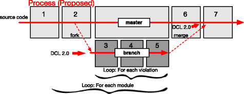
Defined process for the case study
-
2.
Source code preparation.
-
3.
Architecture formalization.
-
4.
Architectural verification and violation analysis.
-
5.
Violations removal.
-
6.
Generate a new system’s version.
-
7.
Monitoring and evolution.

1. Development team preparation: In this step, we explained the DCL 2.0 language to the team. We also separated the development team into two groups. Group 1 was composed of architects who are responsible to specify the system architecture in DCL 2.0. Group 1 is also responsible to refactor the code to remove architectural violations. Group 2 is composed of developers that keep the standard software development process followed by the company.
2. Source code preparation: We extracted the current and previous versions of the source code for the target system. All the versioning information is stored into a database for further analyses.
3. Architecture formalization: Group 1 (architects) specifies the system’s architecture using DCL 2.0 language and our tool (DCL2Check), which should map architectural components into code elements. The architects specified the system based on the common stereotypes employed by their company to map the components. For instance, a PersonCtr class (as well as any class with the “Ctr” suffix in their name) should be mapped to the Control component.
4. Architectural verification and violation analysis: After the architecture formalization (step 3), the architects (group 1) execute DCL2Check to compare the planned architecture to the implemented code and to reveal the architectural violations.
Since the architects are working on a large system, there is a strategy to handle violations. The strategy is to verify each module in sequence—starting with the module with the smaller number of dependencies—, to analyze the violations, and to schedule for the code or architectural changes.
5. Violations removal: The violations found on the last step are removed. More specifically, each violation is fixed, documented, and committed to the repository. The violation can be removed by modifying artifacts to fit into planned the planned architecture, or the architectural specification can be adapted. Group 1 repeats steps 2, 3, 4, and 5 for each module until all system’s violations are fixed.
6. Generate a new system’s version: After all violations are removed from the secondary branch, the changes are pushed to the main branch to create a new version of the system. After joining the two branches, DCL2Check is installed on group 2 machines to inhibit further violations.
7. Monitoring and evolution: After group 1 creates a new system’s version, the resulting architecture is presented to the entire development team. We also analyze the resulting architecture for the case study. After that, the architects keep track of the system’s architecture for adaptation, evolution, and correction. The architects should also aid the developers to understand the planned architecture and the violation warnings provided by DCL2Check.
Case study execution
Team preparation
We explained DCL 2.0 to the development team and divided them into two groups: group 1 with two architects and group 2 with eight developers.
Source code preparation
The development company, PRODEMGE, employs two major tools: (i) IBM-RTC (jazz.net/products/rational-team-concert) (Rational Team Concert) and (ii) Maven (maven.apache.org). The first tool is used for version control and the second tool for dependencies management. The tools were used to manage source code artifacts (e.g., java, js, and xml files) as well as architectural specification (e.g., asml files).
Architectural formalization
SSC-ADMIN system is divided into layers, where each layer is an independent module responsible for a specific architectural functionality. The DCL 2.0 specification followed the same decomposition into layers, i.e., the architects created DCL specification for each layer of the SSC-ADMIN system. The system layers are the following: common, domain, interfaces, infrastructure, business, and web. Each of those layers is associated with an Eclipse project. Figure 12 shows the layers and the Eclipse projects.

a, b Component layers for SSC-ADMIN system
According to our methodology, the common layer was the first to be formally specified because it has the smallest number of dependencies. On the other hand, web was the last to be specified because it has the largest number of dependencies.
The architects used the existing documentation to perform the mapping of the system architecture into code. The time spent in the mapping was 2 weeks (i.e., 80 man/h) because the documentation was incomplete and consequently required more time from the architects to reach a consensus on the planned architecture. The architects used naming standards for the mapping because it is less intrusive than annotating the source code. The Java classes were mapped according to their layer. There were JavaScript and XML files that also needed to be mapped into architectural components by the architects.
Listing 4 shows the final architectural specification defined in DCL 2.0 for the domain layer. We made the architectural specifications for the remaining layers public available (https://github.com/aserg-ufmg/sbcars2016). We can observe the mapping of classes into components by using the matching keyword. In lines 7 and 8, the mapping defines the Entity and AudityEntity components, respectively. More specifically, the declarations state that any artifact whose name ends with VO belongs to component Entity, and any artifact whose name ends with AudVO belong to the AuditEntity component. For example, class UserVO belongs to the Entity component, and the AuditoryAudVO class belongs to the AuditEntity component. It is important to highlight that DCL 2.0 tool always matches artifacts to the most related component according to its specification pattern. For instance, even though AuditoryAudVO could match the pattern defined for Entity, it has a much higher correlation to the pattern defined for AuditEntity and hence it is assigned to the AuditEntity component.
Almost every component from the target system were mapped by using naming standards. However, there were a few cases were we mapped components by their file extension. Table 4 reports the number of components and the coverage percentage for each layer. We can see that the coverage may vary greatly for each module. The main reason for the coverage to be lower in smaller projects (e.g., common and infrastructure) is because the architects decided to ignore configuration files related to IDE and integration plugins (e.g., Maven, JBoss, and RTC). Therefore, for smaller projects, the ignored files have a bigger impact on its coverage.
Architectural verification and violation analysis
In this step, the architects define the constraints modeling the relations between modules. Table 5 reports the layers, number of constraints, and the number of references specified in DCL 2.0. For example, Listing 5 presents the Entity component (previously mentioned in Listing 4)  after the architects defined constraints indicating that entities should be serializable (line 4) and must extend BaseVO (line 5). Moreover, the architects noted a great amount of repeated references to external components (147 to be exact) during the definition of architectural rules. For this reason, we advised the architects to specify components related to frameworks, APIs and Java standard libraries into a specific project to promote reuse and decouple these external components.

In the previous step (architectural formalization), the hierarchical restrictions were already defined because the architectural specification implicitly imposes restrictions to insert components to the structure. Therefore, code artifacts that do not fit into a hierarchical model represent violations.
At first, we observed a high number of structural violations (91%) when compared to number of relation violations (9%). The architect analysis detected two deficiencies: (i) code elements that did not have corresponding architectural components, e.g., FunctionalTypeTest class was considered to be part of an unknown component; and (ii) code elements that do not fit to the naming standards, e.g., classMailService had the characteristics of a persistence class and hence it was renamed to NotificationDAO. More specifically, in the PRODEMGE company all helper and testing classes are considered to be a part of system architecture and hence these classes should be modeled into relevant architecture components.
Violations removal
The system showed a high number of violations of two types: unknown component and unknown reference. For this reason, the architects followed two major actions: (i) alter and adapt the architectural specification in DCL 2.0; and (ii) adjust the source artifacts by refactoring the artifacts that do not fit the architectural components.
After that, the architects started to remove the remaining violations until 80% were fixed. A portion of the violations could not be removed because they were considered high risk. Therefore, the architects used the filter feature from DCL 2.0 to avoid these violations to be reported to the development team. However, these high-risk violations were documented and presented to the project managers. The project managers assured they will make plans to carefully remove these violations in the near future. Most of these violations were structural violations occurring in non-java artifacts, which corroborates our hypothesis that it is not sufficient to apply architectural conformance only to the main source code language.
Generate a new system’s version
After the architects removed the violations, they were required to join the source code branches. The modules went through another architectural conformance check to capture new possible violations. In total, 11 new violations were detected and removed. After the refactoring, we created a new version for the architectural specification and the source code. Then, we installed DCL2Check in group 2 (developers) machines to assure the architectural conformance from this point forward.
Monitoring and evolution
In the first weeks, the architects identified code violations that should not be occurring since DCL2Check tool was installed in the developers’ computers. The architects verified the problem and realized that the developers were disabling the validation tool in Eclipse IDE for performance issues. On average, the tool required between one and eight seconds (usually, one second for small modules and eight for bigger ones).
To avoid this issue, we adapted the DCL2Check with the possibility to perform a architectural verification on demand or when the project is built (i.e., a complete project compilation) besides the incremental just-in-time verification. We already described those verification options in section 2, respectively as off-line feedback and build feedback. Moreover, since there was no guarantee that developers would use the tool, the builder (development team member responsible to generate a new system’s version) was now required to use DCL2Check. The project manager also defined that the builder should not accept architectural violations when generating new versions. This step lasted 8 months, and 39 violations were avoided.
Results
The results presented in this section are extracted from the development history of the target system, between June 2013 and April 2016 (35 months). The architectural specifications and violations removal process began in July 2, 2015 and lasted until August 27, 2015 (58 days). During this period, DCL 2.0 was employed to reveal violations that may have occurred since the initial system development. After the violations removal, the DCL 2.0 verification tool was installed on the development team computers. We followed this step from September 2015 to April 2016 (8 months).
As we previously discussed, there was a high number of architectural violations of two types: unknown component and unknown reference. Figure 13 reports the violations found by our tool and classified them into three categories: (1) unknown component and unknown reference violations; (2) other DCL 2.0 violations; and (3) DCL 1.0 violations. We can observe that other types of violations increases when we remove violations from category 1 (i.e., unknown component and unknown reference violations). This observation reinforces our hypothesis that unknown component and unknown reference violations may, in fact, mask other types of violations.

Violations found before and after the removal step
Figure 14 reports the number of commits that presented (or not) architectural violations. In this figure, we highlight two dates: (i) July 2015 marks the beginning of DCL 2.0 specification, and (ii) September 2015 marks when DCL 2.0 verification started. There is no direct relation between the number of commits and the number of violations. For instance, Fig. 14 shows periods with high number of commits and few violations, and vice versa.

Commits and violations
We observed a trending pattern of new violations during the development. More specifically, the first 2 months showed in Fig. 14, 2013/06 (June) and 2013/07 (July), show a great number of violations because during this time period most classes were added to the project.
During January 2015 to April 2015, two main factors related to evolution maintenance contributed to the increase in violations: (i) the system was enhanced with new features related to functional requirements; and (ii) new code added for a JSON framework extension. Figure 15 shows the number of features added to the system. We can observe a positive relation between adding new features and introducing architectural violations. We run Spearman’s rho test to measure the strength of this association (from July 2013 to June 2015), which was considered strong (r h o = 0.694). The violations were accumulated until DCL 2.0 was incorporated to the development process, after that, violations were removed constantly. In summary, adding new features creates more violations than periods where corrective maintenance were applied to existing features. We can also observe the importance of an architectural conformance in the development process because after August 2015 the number of violations greatly decreases.

New features and violations
Figure 16 shows changes and violations on the source related to developers’ profile. We can see that all profiles introduce architectural violations. Moreover, if we observe violations related to complex code changes, senior developers introduced approximately ten times more violations than other profiles. The reason for this occurrence is because senior developers are delegated to more complex coding tasks, which have a higher probability to impact on the architecture.

Violations complexity by developer
Figure 17 shows the amount of development tasks each profile accomplished. We can see that senior developers are responsible for more tasks than other profiles. If we compare both Figs. 16 and 17, we can notice the more tasks a developer implements on the system, more architectural violations are also introduced.

Implementation tasks by developer
Discussion
In this section, we answer our research questions defined in the beginning of this case study.
RQ#1.1) Why do architectural violations occur?
When we analyze the results, we can see that architectural violations can occur in the earlier stages of software development. Moreover, the architectural degradation does not fit into a linear pattern. The results show a clear relation between violations and adding new features to the system, i.e., code changes that adds new functionalities are more likely to spawn architectural violations than those changes that only maintain an already implemented functionality.
There is another important lesson regarding the violations related to developers’ skill. Generally, all profiles introduce architectural violations. However, more skilled developers (seniors) are more involved in complex tasks, which makes them responsible for introducing more complex violations. We asked the developers and architects from the development team and according to them the main causes of introducing architectural violations are the following: (i) lack of knowledge and understanding of the architectural conventions adopt for the system, mostly because the extensive documentation; and (ii) lack of architectural evolution, because developers when faced with a limitation imposed by the planned architecture would built their own solution without asking the architect and adapting the architecture.
The developers also associated stressing over project’s deadlines as a secondary factor to architectural divergence. Developers stated that they do not contradict architectural conventions on purpose. However, the developers also stated that the pressure and stress related to fulfill work deadlines may have inhibited them to seek more information about the architecture when needed.
RQ#1.2) How does the development team handle the violations?
When we analyzed the history of changes for the system, we can see that violations were removed even before the installation of our tool. Therefore, the development team fixed violations without a proper process or planning. However, most of the violations removed before DCL 2.0 had low complexity, which leaves higher complexity violations present in the system. The developers stated the main factor to not remove more complex violations is the risk to introduce bugs into the system.
The developers also stated that not having tool support to find architectural violations since the beginning of the development as a difficulty factor to not removing them, mainly because manual code inspection for architectural violations is difficult and costly.
RQ#2.1) Can DCL 2.0 be used to avoid architectural violations?
When we consider the time of the case study (10 months) where we installed our DCL2Check tool to aid in architectural conformance process, the results indicate that the development team was able to control and handle architectural violations. Even though new features were added to the system and maintenance took place during the evaluated period, the system did not deviate from the planned architectural concepts.
RQ#2.2) Do the new concepts and features introduced by DCL 2.0 improve the architectural verification process?
We observed the following benefits regarding DCL 2.0 new features:
-
Hierarchical and modular modeling proved to be very effective. It provides better ways to specify the system architecture in a more faithful manner. Moreover, we can create independent modules promoting decomposition, and we can specify source artifacts promoting more abstraction levels.
-
New restriction types were invaluable to capture the system’s architectural state (very informal) when we started the study. Moreover, the unknown component and unknown reference violations were essential to model the architectural coverage required by the development team. Another evidence, which highlights the importance of the new violations, is how other violations were revealed once the developers removed unknown component and unknown reference. Therefore, these violations may hide other types of violations, which could be discovered by DCL 2.0.
-
Cross reference between modules was important to avoid errors and also to speed up the architectural specification process.
-
The reusability improved because the architectural definitions are completely independent from the target system. Therefore, the specifications can be reused in other software projects. However, we acknowledge that we need to perform experiments in other systems to better evaluate reusability aspect of DCL 2.0.
-
Decoupling between the system and architecture specification provided an easier architectural evolution. More specifically, the decoupling allowed the development team to employ configuration management techniques to the architectural specification. This characteristic is important to control the architectural evolution, especially because each architectural module had eight versions (on average) during the study period.
RQ#2.3) Can DCL2Check tool be used in real software development process to perform architectural verification?
Although this research question may be consider only technical aspects, we claim these aspects can be important when someone decides to adopt our tool or not. During the study, we adapted our tool to the real development scenario, e.g., we created new forms of verification to address performance issues the developers faced when using DCL2Check.
The new visualizations provided by DCL 2.0 (architectural and log visualization), and the functionality of validation when the project is built (build feedback verification option presented in the “Architectural verification” section) were important to the architectural specification process. Moreover, the tool editor provided cross-reference, error verification, and auto-complete new features to facilitate the task of architectural specification. We also integrated our tool with Maven to better distribute and control different versions of the modeled architecture. Finally, the tool was incorporated and used in a real architectural verification process.
Threats to validity
In this section, we identify and classify threats to validity in our evaluation.
External validity
We used for our experiments one proprietary system. We cannot claim that different systems will provide similar results. Therefore, our results may not reflect other proprietary or open-source systems. We tried to mitigate this threat by choosing a large system developed by real technology company.
Construct validity
For the evaluation, we relied on the system architects (group 1) for most of the experimental steps detailed in the “Process definition” section. The architects defined the architectural specification and rules based on company standards. The architects were also responsible to fix the architectural violations from the system before making the architectural conformance tool available to the developers. Therefore, if different architects participated in the experiment, the modeled architecture and, consequently, the violations found and fixed may also be different. We mitigate this threat by selecting a development team with experienced architects, who were knowledgeable in the company standard architectural specifications. Therefore, if other architects with similar experience from the same company participated in our experiment, it would have little effect on the results.
Internal validity
As we stated in the construct validity, our evaluation relies on architects. Therefore, they could be affected positively or negatively during the experiment. We mitigated this threat by conducting and monitoring the experiment for approximately eight weeks (58 days to be exact). Therefore, it is less likely for the architects to be affected (either positively or negatively) throughout the whole experiment in a way that would significantly impact the experiment.
Conclusion validity
Although DCL 2.0 was successful in helping the development team to find and fix architectural violations, we cannot guarantee that another architectural conformance tool would provide similar or better results. When compared architectural conformance techniques (the “Conformance techniques comparison” section) only few of those partially supports the detection of structural violations. Since most of the violations found in the experiment were structural ones, we claim that other techniques may not perform better than DCL 2.0.
Related work
We found several approaches and techniques proposed to address or solve architectural erosion in systems. We divided the related work into two main categories: (i) architectural conformance; and (ii) empirical studies.
Architectural conformance
Reflexion models compare two models, low abstraction level model (i.e., source code) and a higher abstract level model (i.e., conceptual and architectural elements) of the system [11]. The models require a mapping task between the two models to compare them. When we compare both models, the reflexion model is created in which three types of relations between the models are revealed: convergence, divergence, and absence. The main disadvantage of reflexion models is the lack of reusability [19]. By contrast, when we designed DCL 2.0, reuse was one of the main concerns for the language.
Another study implements a modular and hierarchical specification based on slices called Vespucci [8]. A slice is a portion or block of the specified architecture, and it also helps to control the dependencies among other blocks. Slices are composed of smaller conceptual blocks called ensembles. The authors argue that this approach allows the formalization of architectures in different abstraction levels, which facilitates architectural maintenance and evolution because the specification is modular and hierarchical. Their technique combines box-and-line diagrams to define the architectural structure and a textual language to map the source code into the architecture. Their technique also controls relational violations between components, although it does not handle or support structural violations. On the other hand, DCL 2.0 offers dependency control among modules and also provides ways to model structural relations.
Dependency structure matrix (DSM) was introduced to explain the importance of modular projects in the hardware industry [22]. Another research shows that DSM can also be applied in the software industry [21]. DSM is based on a square matrix, which the intersections among lines and columns denotes a relation between components (classes) in an object-oriented system [7, 22]. An interesting aspect of this technique is the possibility to visualize in matrix how much a component is associated with another one. DSM also supports the grouping of components into modules, which facilitates analysis among component relations. The grouping strategy also allows architects to work with DSM in a hierarchical manner, which they could use to analyze the architecture in different abstraction levels. DSM can also be used in conjunction with architectural rules. However, DSM does not support a formal architectural specification, which hinders the reuse. On the other hand, DCL 2.0 tries to promote reuse, not only by allowing an easier specification of the formal architecture, but also by providing modular and hierarchical specifications that can be used in other systems.
The.QL language, which was based on SQL, aims to locate specific source code elements [23]. This language can be used for architectural conformance to generate queries to detect coding patterns that do not follow the planned architecture. This technique works only at source code, which is a low level abstraction and that may make difficult to understand the architecture. DCL 2.0 provides more ways to model different abstraction levels to improve the understanding and evolution of the architecture.
Design test is a technique to verify the architectural conformance by using automated tests similar to the ones done by unit testing [24]. This technique also suffers from a low abstraction level, which hinders the architectural understanding. As we previously discussed, DCL 2.0 does not suffer from this disadvantage because it provides architectural specification on different abstraction levels.
Framework-specific model language (FSML) contrasts with other approaches because it does not control dependencies. Instead, FSML relies on strict framework instantiation model to assure the architectural conformance. Each FSML contains rules and information required to correctly use a framework. The approach maps every framework extension point and its instantiation rules to verify the architecture on framework-based systems [25, 37]. Unlike DCL 2.0, this technique does not address violations among component relations.
ArchLint is an approach to verify the architectural conformance that does not require a manual specification of the architectural rules [9, 26]. The technique requires a system versions history and a high-level document modeling the system. ArchLint combines static code analysis, change history analysis, and a set of heuristics to classify architectural dependencies (or the lack of dependencies). This approach contrasts with DCL 2.0 because the architectural restrictions on ArchLint are not specified, i.e., ArchLint automatically extracts those rules from the system. On the other hand, ArchLint does not handle structural violations in contrast to DCL 2.0.
OCL [27] is a UML standard to model object-oriented architectural constraints. OCL allows the representation of functional and non-functional requirements on objects and expressions on a UML model. One of the problems faced by OCL is its difficulty to reuse constraints [28]. Another problem is the lack of usability [38]. Bajwa et al. [38] try to improve the OCL usability by writing the specifications in natural language and then converting it to OCL. They built a tool, called OCL-Builder, to perform the conversion from Natural Language to OCL constraints. DCL 2.0 was designed to be easier to adopt and use, unlike OCL which does not favor them. When we compare DCL 2.0 with Bajwa et al. [38] extension, their new natural language constraints are better than OCL but it still lacks usability and requires users to learn a new definition language. DCL 2.0 was also built to favor reuse which OCL, and its variations do not take into account.
Armani [30] is a language to model software architecture designs. The author presents the full scope of Armani in his work. However, the author does not perform any form of evaluation. Even the examples provided in the report are small and lack usability of a real development scenario. For DCL 2.0, we presented the language but we also evaluated our approach in a real software development scenario.
Alloy [29] is another architectural language that its architectural specification into another model to perform an automatic conformance check. The authors use concepts from UML 2.0 and the Acme ADL to specify the architecture. Alloy reads this specification and generates another document with its model for automatic verification. Although, the author provide some examples of use, they did not evaluate their approach. Another problem faced Alloy and discussed by authors was the performance. The authors acknowledged that a large model may take some time, but they did not specify what that time would be. On the other hand, for our paper we showed an evaluation in a real scenario and we collected and presented the performance information for such tests.
CLACS [28] is an architectural language specifically designed to be more easy to reuse its specifications and constraints for other projects. The authors hypothesized that component-based concepts can be used to make the architectural specifications more resusable. The authors also empirically evaluate their approach focusing more on the reusability aspect. CLACS and DCL 2.0 are similar as both have reuse as a major concern for their design, and both were empirically evaluated. However, DCL 2.0 also shows concerns for other aspects neglected by CLACS (e.g., structural constraints, visualization, etc.). Another difference is that DCL 2.0 was evaluted in a real sofware development scenario, while CLACS collected its data from other sources.
Empirical studies
Rosik et al. [4] evaluated a real software development for commercial purposes where reflexion models were employed to detect architectural violations. The authors concluded in their evaluation that violations are not removed from the source code even if they are detected. The authors reported that the evaluated development team did not felt safe to remove the detected violations. This contrasts with our case study, where architects and developers were encouraged to remove as many violations as possible. As a result, for our case study most detected violations were removed.
Brunet et al. [39] analyzed the Eclipse platform evolution over five years to understand the violations during the development. The authors investigate the architectural rules, the characteristics of the violations, and the developers addressing the violations. They concluded that most restrictions are related to classes (or interfaces) extension control, which contrasts with the majority of the research on architectural conformance that are based on dependencies between components. For our paper, we focus more on the design of DCL 2.0 and the case study. Although we investigate the possible causes for architecture violations, this is not the main focus of this research.
Knodel et al. [6] introduced the concept of constructive conformance verification in reflexion models, i.e., instant feedback is given to developers related to architectural violations. The results indicated the developers inserted 60% less architectural violations when utilizing the approach. DCL 2.0 also offers a just-in-time architectural verification for instant feedback, although we also provide incremental on demand verification for performance issues. When compared to our case study, the project builder could not accept code artifacts with architectural violations. Therefore, developers in our case study stopped inserting architecture violations in new system version.
In another similar work, Knodel et al. [20] argued that prototype tools are not appropriate to evaluate real scenarios. The authors also highlight the necessity to test new approaches in real scenarios before making them available to software companies. We agree with the authors perspective and DCL 2.0 and its tool were applied to a real development scenario in our case study.
In another work, Knodel and Popescu [19] compared reflexion models and two other techniques (relation conformance rules, and component access rules) to assess their applicability on architectural conformance. The authors present 13 different criteria to evaluate each technique and discuss their characteristics. In our paper, we also did our own comparison according to seven characteristics on eight different techniques for architectural conformance.
Wettel et al. [40] proposed a technique to visualize software artifacts in a three dimension environment, called Code City. They also empirically evaluate their technique with 41 participants. The evaluation tries to capture relevant tasks that would occur in real development scenarios. JSCity [41] is a variant implementation of Code City but specialized for JavaScript programs. Code City and its different implementations focus more on the software artifacts (packages, classes, etc.). Our tool the dcl2check does not offer a 3D view, but it can show the artifacts as well as the higher level architectural components related to those artifacts. Moreover, Code City is a tool only for visualization purposes while DCL 2.0 and its tool can be used for architecture conformance as well.
Lutellier et al. [42] compared six techniques used to extract architecture from systems. In the evaluation, the authors employed nine variants of those six techniques to extract the architecture for five systems. This contrasts with our work because DCL 2.0 was designed for architecture modeling and conformance, and it does not extract a system’s architecture automatically.
Merson [43] used a static analysis tool to perform architecture conformance checks. The author applies his approach in a real software development scenario with more than 50 Java EE applications. The size of the development team is large, being composed of 57 employees and 24 interns working over the course of two years. Even though, Merson applied his approach in a real scenario, his evaluation does not analyze further the impact of the architecture conformance (e.g., it is not shown or discussed exactly how many violations his approach managed to capture or prevent). For DCL 2.0, our evaluation scenario is smaller when compared to Merson. However, our analysis of the architecture conformance is presented in more detail.
Terra and Valente [12] applied DCL and the DCLSuite tool as a case study to evaluate architectural conformance on a real system. The main motivation was to verify whether architectural violations occurs when inappropriate dependencies between modules are implemented in the source code. For the experiment, the authors employ the DCLSuite tool on three versions of the target system. They monitored the software and architectural evolution for two earlier versions and they evaluated the third version for their analysis. The results show that DCL identified 179 classes (8% of all the classes for the system) with at least one architectural violation. Finally, the authors discuss DCL positive points as: (i) expressiveness, since DCL supports many architectural restrictions types to cover a wide spectrum of violations; (ii) abstraction level, because DCL offers a module definition to associate lower level elements (source code) to a higher abstraction element (module); and (iii) applicability, as the authors highlight the non-intrusive nature of the DCLSuite tool and how easy it is to learn and use DCL. As we discussed throughout the paper, DCL 1.0 has disadvantages which DCL 2.0 aims to fix. We also presented a case study for a real software development scenario.
Conclusion
Architectural conformance is an important task to detect and reverse architectural erosion. Although there are several techniques to tackle this task, all of them show some negative points, specially regarding the reuse of architectural definitions and the capability to discover structural violations. For this reason, we developed DCL 2.0, which extends the original DCL language by giving support to modular and hierarchical architectural specifications, the detection of structural violations, and the promotion of better reuse. We also describe a DCL 2.0 tool implementation, called DCL2Check, which facilitates its adoption.
We evaluated DCL 2.0 on a large system to verify its applicability on a real software development scenario. We observed the following results regarding architectural erosion phenomenon during our evaluation experiment:
-
Structural violations compromised 91% of all the violations found in the system. Moreover, structural violations can hide or mask other types of violations, since they make it difficult to correctly identify the components. Considering all violations together (even those masked by others), 74% were only detected by the new features introduced in DCL 2.0.
-
Architectural violations occur more frequently in evolution maintenance than corrective maintenance. We can also see a correlation between a set of changes implemented by a developer and the number of architectural violations. However, we could not find a direct correlation between violations and commits.
-
Experienced developers introduce more complex architectural violations than other developers. The reason is because experienced developers handle more complex coding tasks, which are more likely to introduce violations. Moreover, many complex violations are not removed from the system.
-
One of the initial steps to validate the architecture is to identify its components. The risk of introducing architectural violations lessens for well-known components. On the other hand, unknown components and references represent a silent problem that could hide serious violations.
Besides the good results in detecting existing violations, DCL 2.0 also proved important in helping the development team to address violations. After ten months since the installation of DCL 2.0, the number of architectural violations being committed into the system branches was reduced to zero. Based on the presented results, we concluded that DCL 2.0 can have a positive impact on the architectural conformance of systems.
We have the following ideas for future work: (i) new visualization types; (ii) architectural specification that supports fine grained elements (such as methods or attributes); (iii) architectural rules definition based on metrics, e.g., a component must have low coupling; (iv) a catalog of architectural references; and (v) another experiment comparing DCL 2.0 against other techniques w.r.t. learning curve effect and applicability difficulty, for example.
Abbreviations
- ADL:
-
Architecture description language
- DCL:
-
Dependency constraint language
- DSM:
-
Dependency structure matrix
- FSML:
-
Framework-specific model language
- OCL:
-
Object constaint language
- SCQL:
-
Source code query language
References
Shaw M, Clements P (2006) The golden age of software architecture. IEEE Softw 23(2): 31–39.
Kruchten P (2008) What do software architects really do?. J Syst Softw 81(12): 2413–2416.
Knodel J, Lindvall M, Muthig D, Naab M (2006) Static evaluation of software architectures In: 10th European Conference on Software Maintenance and Reengineering (CSMR), 294–304.. IEEE Computer Society, Washington.
Rosik J, Le Gear A, Buckley J, Babar MA, Connolly D (2011) Assessing architectural drift in commercial software development: a case study. Softw Pract Experience 41(1): 63–86.
Kruchten P (1995) The 4+1 view model of architecture. IEEE Softw 12(6): 42–50.
Knodel J, Muthig D, Rost D (2008) Constructive architecture compliance checking - an experiment on support by live feedback In: 24th International Conference on Software Maintenance (ICSM), 287–296.. IEEE Computer Society, Washington.
Sangal N, Jordan E, Sinha V, Jackson D (2005) Using dependency models to manage complex software architecture In: 20th Conference on Object-Oriented Programming, Systems, Languages, and Applications (OOPSLA), 167–176.. ACM, New York.
Mitschke R, Eichberg M, Mezini M, Garcia A, Macia I (2013) Modular specification and checking of structural dependencies In: 12th International Conference on Aspect-oriented Software Development (AOSD), 85–96.. ACM, New York.
Maffort C, Valente MT, Anquetil N, Hora A, Bigonha M (2013) Heuristics for discovering architectural violations In: 20th Working Conference on Reverse Engineering (WCRE), 222–231.. IEEE Computer Society, Washington.
Passos L, Terra R, Valente MT, Diniz R, Mendonca N (2010) Static architecture-conformance checking: an illustrative overview. IEEE Softw 27(5): 82–89.
Murphy G, Notkin D, Sullivan K (1995) Software reflexion models: bridging the gap between source and high-level models In: 3rd Symposium on Foundations of Software Engineering (FSE), 18–28.. ACM, New York.
Terra R, Valente MT (2009) A dependency constraint language to manage object-oriented software architectures. Softw Pract Experience 39(12): 1073–1094.
Bessa S, Valente MT, Terra R (2016) Modular specification of architectural constraints In: X Simpósio Brasileiro de Componentes, Arquiteturas e Reutilização de Software (SBCARS), 31–40.. IEEE Computer Society, Washington.
Van Eyck J, Boucké N, Helleboogh A, Holvoet T (2011) Using code analysis tools for architectural conformance checking In: 6th International Workshop on SHAring and Reusing Architectural Knowledge (SHARK), 53–54.. ACM, New York.
Terra R, Valente MT, Czarnecki K, Bigonha RS (2015) A recommendation system for repairing violations detected by static architecture conformance checking. Softw Pract Experience 45(3): 315–342.
Zapalowski V, Nunes I, Nunes DJ (2014) Revealing the relationship between architectural elements and source code characteristics In: 22th International Conference on Program Comprehension (ICPC), 14–25.. ACM, New York.
Koschke R, Simon D (2003) Hierarchical reflexion models In: 10th Working Conference on Reverse Engineering (WCRE), 36–45.. IEEE Computer Society, Washington.
Knodel J (2002) Process models for the reconstruction of software architecture views. PhD thesis, Universität Stuttgart.
Knodel J, Popescu D (2007) A comparison of static architecture compliance checking approaches In: 6th Working IEEE/IFIP Conference on Software Architecture (WICSA), 12–12.. IEEE Computer Society, Washington.
Knodel J, Muthig D, Haury U, Meier G (2008) Architecture compliance checking-experiences from successful technology transfer to industry In: 12th European Conference on Software Maintenance and Reengineering (CSMR), 43–52.. IEEE Computer Society, Washington.
Sullivan KJ, Griswold WG, Cai Y, Hallen B (2001) The structure and value of modularity in software design. ACM SIGSOFT Softw Eng Notes 26(5): 99–108.
Baldwin CY, Clark KB (1999) Design rules: the power of modularity. MIT Press, Cambridge.
De Moor O, Verbaere M, Hajiyev E, Avgustinov P, Ekman T, Ongkingco N, Sereni D, Tibble J (2007) Keynote address: QL for source code analysis In: 7th IEEE International Working Conference on Source Code Analysis and Manipulation (SCAM), 3–16.. IEEE Computer Society, Washington.
Brunet J, Guerrero D, Figueiredo J (2009) Design tests: an approach to programmatically check your code against design rules In: 31st International Conference on Software Engineering (ICSE), 255–258.. IEEE Computer Society, Washington.
Antkiewicz M, Czarnecki K (2006) Framework-specific modeling languages with round-trip engineering In: 9th International Conference on Model Driven Engineering Languages and Systems (MoDELS), 692–706.. Springer-Verlag, Berlin.
Maffort C, Valente MT, Terra R, Bigonha M, Anquetil N, Hora A (2016) Mining architectural violations from version history. Empir Softw Eng 21(3): 854–895.
(2012) OMG: object constraint language (OCL), Version 2.3.1. http://www.omg.org/spec/OCL/2.3.1/. Accessed 20 May 2017.
Tibermacine C, Sadou S, Ton That MT, Dony C (2016) Software architecture constraint reuse-by-composition. J Futur Gener Comput Syst 61(C): 37–53.
Kim JS, Garlan D (2006) Analyzing architectural styles with alloy In: ISSTA 2006 Workshop on Role of Software Architecture for Testing and Analysis. ROSATEA ’06, 70–80.. ACM, New York.
Monroe RT, Overview A (1998) Capturing software architecture design expertise with armani. Technical report, Carnegie Mellon University.
Terra R, Valente MT, Czarnecki K, Bigonha RS (2012) Recommending refactorings to reverse software architecture erosion In: 16th European Conference on Software Maintenance and Reengineering (CSMR), 335–340.. IEEE Computer Society, Washington.
Miranda S, Rodrigues E, Valente MT, Terra R (2016) Architecture conformance checking in dynamically typed languages. J Object Technol 15(3): 1–34.
Parnas DL (1972) On the criteria to be used in decomposing systems into modules. Commun ACM 15(12): 1053–1058.
Tonella P, Torchiano M, Du Bois B, Systä T (2007) Empirical studies in reverse engineering: state of the art and future trends. Empir Softw Eng 12(5): 551–571.
Terra R, Valente MT, Czarnecki K, Bigonha RS (2012) Recommending refactorings to reverse software architecture erosion In: 16th European Conference on Software Maintenance and Reengineering (CSMR), 335–340.. IEEE Computer Society, Washington.
Tvedt RT, Lindvall M, Costa P (2002) A process for software architecture evaluation using metrics In: 27th Annual NASA Goddard/IEEE, Software Engineering Workshop, 191–196.. IEEE Computer Society, Washington.
Lee H, Antkiewicz M, Czarnecki K (2008) Towards a generic infrastructure for framework-specific integrated development environment extensions In: 2nd Workshop on Domain-Specific Program Development (DSPD), 1–6.
Bajwa IS, Bordbar B, Lee MGOcl constraints generation from natural language specification In: 2010 14th IEEE International Enterprise Distributed Object Computing Conference, 204–213.. IEEE Computer Society, Washington.
Brunet J, Murphy GC, Serey D, Figueiredo J (2015) Five years of software architecture checking: a case study of Eclipse. IEEE Softw 32(5): 30–36.
Wettel R, Lanza M, Robbes R (2011) Software systems as cities: a controlled experiment In: Proceedings of the 33rd International Conference on Software Engineering. ICSE ’11, 551–560.. ACM, New York.
Viana M, Hora A, Valente MT (2017) Codecity for (and by) JavaScript. Comput Res Repository (CoRR)abs/1705.05476: 1–9.
Lutellier T, Chollak D, Garcia J, Tan L, Rayside D, Medvidović N, Kroeger R (2015) Comparing software architecture recovery techniques using accurate dependencies In: 37th International Conference on Software Engineering. ICSE ’15, 69–78.. IEEE Press, Piscataway.
Merson P (2013) Ultimate architecture enforcement: custom checks enforced at code-commit time In: Proceedings of the 2013 Companion Publication for Conference on Systems, Programming, & Applications: Software for Humanity. SPLASH ’13, 153–160.. ACM, New York.
Acknowledgements
Our research has been supported by CAPES, FAPEMIG, and CNPq.
Funding
Funding information is not applicable for this paper.
Availability of data and materials
The dataset supporting the conclusions of this article belong to a government branch with sensitive information, we cannot publicly share this data. We ask that researchers contacts us directly for the data.
Author information
Authors and Affiliations
Contributions
HR and RSD wrote this manuscript. HR, RSD, and SB extended the original work with new content for this manuscript. RT and MTV revised the manuscript. All authors read and approved the final manuscript.
Corresponding author
Ethics declarations
Competing interests
The authors declare that they have no competing interests.
Publisher’s Note
Springer Nature remains neutral with regard to jurisdictional claims in published maps and institutional affiliations.
Rights and permissions
Open Access This article is distributed under the terms of the Creative Commons Attribution 4.0 International License(http://creativecommons.org/licenses/by/4.0/), which permits unrestricted use, distribution, and reproduction in any medium, provided you give appropriate credit to the original author(s) and the source, provide a link to the Creative Commons license, and indicate if changes were made.
About this article

Cite this article
Rocha, H., Durelli, R.S., Terra, R. et al. DCL 2.0: modular and reusable specification of architectural constraints. J Braz Comput Soc 23, 12 (2017). https://doi.org/10.1186/s13173-017-0061-z
Received:
Accepted:
Published:
DOI: https://doi.org/10.1186/s13173-017-0061-z